Table Of Content

All printed circuit boards essentially perform similar functions, but there are three main types — rigid, rigid-flex, and flex — which all differ in terms of design and construction. Instead, use a complete ground plane below your components, and do not physically break the ground plane up into sections. Keep the analog components with other analog components operating at the same frequency.

Working with Power Supply Design Tools
Long traces can pick up electromagnetic radiation from other sources, which can cause interference and noise. If you can't find the components you need in the library, submit a request and EasyEDA will create the library drawings for you free of charge. You can easily view all team project status and logs in the workspace. New interface, web-based tool, high efficiency, no need to download.
PCB Design Software Features
The integrated LibrePCB Fab service also allows for easy PCB ordering through Aisler with a portion of profits fed back into the development of the program. But with over three decades of development and countless improvements over the years, it’s a powerful PCB design tool that rivals many of the paid options. Suitable applications include single-board computers, motor controllers, custom mechanical keyboards, drones, smartwatches, low-power cameras, and much more. That’s what we reveal in this guide, where we review the top PCB design software tools out there to help you find the right match – and we have specific recommendations based on your current needs. The bare PCB is made up of land patterns for components to be attached/soldered on to the PCB.
PCB DesignResources
The standard workflow in PCB design focuses on taking an engineered design, finishing a physical PCB layout, and preparing the finalized design for manufacturing. The state of design in electronics today is at its most complex and intense as ever before. Design teams must deliver more complex products on even more compressed schedules, but they lose valuable time with unproductive tasks. Connect them through all engineering disciplines and give them best-in-class solutions to thrive with a collaborative approach to electronic systems design. Download my guide with all the steps you need to design your first printed circuit board (PCB) from scratch.
At this point in the design, your goal is to place components to ensure that the design is solvable, meaning it can be routed easily. Therefore, it’s best to avoid doing any routing until after the components are placed and placement is approved. If you route before all the components are placed, it’s inevitable that you’ll have to change the routing.
Step 3: Trace Routing
One of the first choices to make in PCB design is the number of layers to use. For example, the complexity of your circuit, manufacturing costs, pin density, signal layers, operating frequency, and PCB turnaround time, among others. A power plane is a large layer of copper that is connected to the circuit’s Vcc terminal. Power planes are usually added to the top of a single layer PCB or to the middle of a two layer PCB.
Though a deep program, Altium Designer’s user-experience is highly rewarding for new and experienced PCB board designer experiences alike. It offers a design environment built from the ground up for a streamlined custom circuit board design process within a single, unified printed circuit board layout environment. Note that many design processes state that you should run design rule checks at the end of the board design phase while preparing for manufacturing. If you use the right design software, you can run checks throughout the design process, which allows you to identify design potential problems early and correct them quickly. Altium Designer includes a number of important tools to help make your routing experience easier and more productive. There is an autorouter engine that uses a modern algorithm to route traces, as well as traverse layer pairs with vias.
It is also appropriate to separate components that will dissipate a lot of heat on the board into different areas. The idea behind separating these high-power components is to equalize the temperature around the PCB layout, rather than to create large hotspots in the layout where high-temperature components are grouped. This can be accomplished by first finding the “thermal resistance” ratings in your component’s datasheet and calculating the temperature rise from the estimated heat dissipation. Heatsinks and cooling fans can be added to keep component temperatures down.
It will also help if you ever need to debug the board while testing. You can also add a company logo and part numbers using the image tools and text tools in the PCB Editor. These elements need to be placed in the Top Overlay or Bottom Overlay layers in the PCB layout.
SimSolid circuit solvers launched by Altair for PCB design - Develop3D
SimSolid circuit solvers launched by Altair for PCB design.
Posted: Thu, 04 Apr 2024 09:02:52 GMT [source]
After you’ve made your selections, click “Save to Cart” and you’ll be taken to a page where you can enter your shipping address and billing information. Most PCB manufacturers will let you order different layer thicknesses. Copper weight is the term manufacturers use to describe the layer thickness, and it’s measured in ounces. The thickness of a layer will affect how much current can flow through the circuit without damaging the traces. Trace width is another factor that affects how much current can safely flow through the circuit (discussed below). To determine safe values for width and thickness, you need to know the amperage that will flow through the trace in question.

1) Display the Libraries panel by clicking the Panels button at the bottom right of the software, and select Libraries. Refer to the rough schematic sketch above for the general layout of the circuit, and place 2N3904 transistors Q1 and Q2. Choose or create the project directory and save the project withthe name Multivibrator. The components you use will also have an effect on the size of the finished PCB.
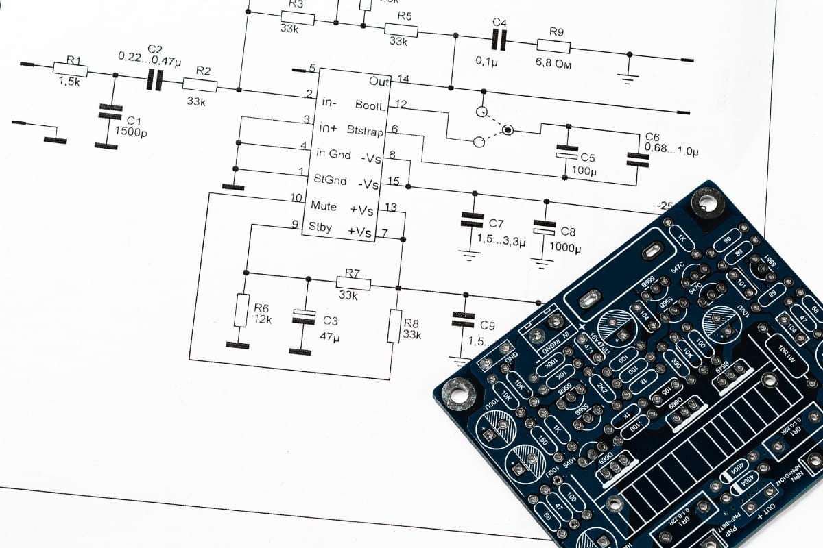
You can comfortably violate this design rule and set your limit lower as most fabricators will require minimum spacing of approximately 5 mils. Make sure to check clearances on your fabricator’s capabilities sheet before you start messing with design rules. Once you’ve got a high-level view of the design process, read the link below to see how the PCB design workflow unfolds and the standard set of tasks every designer must perform to finish a new circuit board. You need to transfer your schematic diagram into a drawing of your printed circuit board.
This unwanted electromagnetic energy is called electromagnetic interference and this can be harmful to sensitive circuits. When placing individual components like resistors, capacitors, or transistors into a PCB layout, arrange them in a way that minimizes the length of the conducting traces. When designing a PCB, you should group the components in each sub-circuit together in different areas of the PCB.
It’s completely free to use, and unlike CircuitMaker, Fritzing doesn’t limit how many projects you can make with it. The focus on ease of use is bettered by a library of free teaching resources and lessons that help students learn and understand fundamental concepts of PCB design and complete their first project. And Upverter is arguably the best option for first timers or educators looking for a shallow learning curve and easy introduction to PCB design.
This ensures everything in your design is synchronized and the design rules engine in your software will read your design data correctly. The mechanical engineer provides the physical packaging or envelope with all the physical requirements and constraints. Then, a layout specialist (electrical designer) designs the PCB layout, which is a result of a collaborated effort by multiple disciplines. This specialist has always functioned as the hub or focal point of the project team for gathering all required inputs/requirements that are to be implemented into the design of the PCB. Your time is valuable, which is why you want to design your printed circuit board correctly from the start.
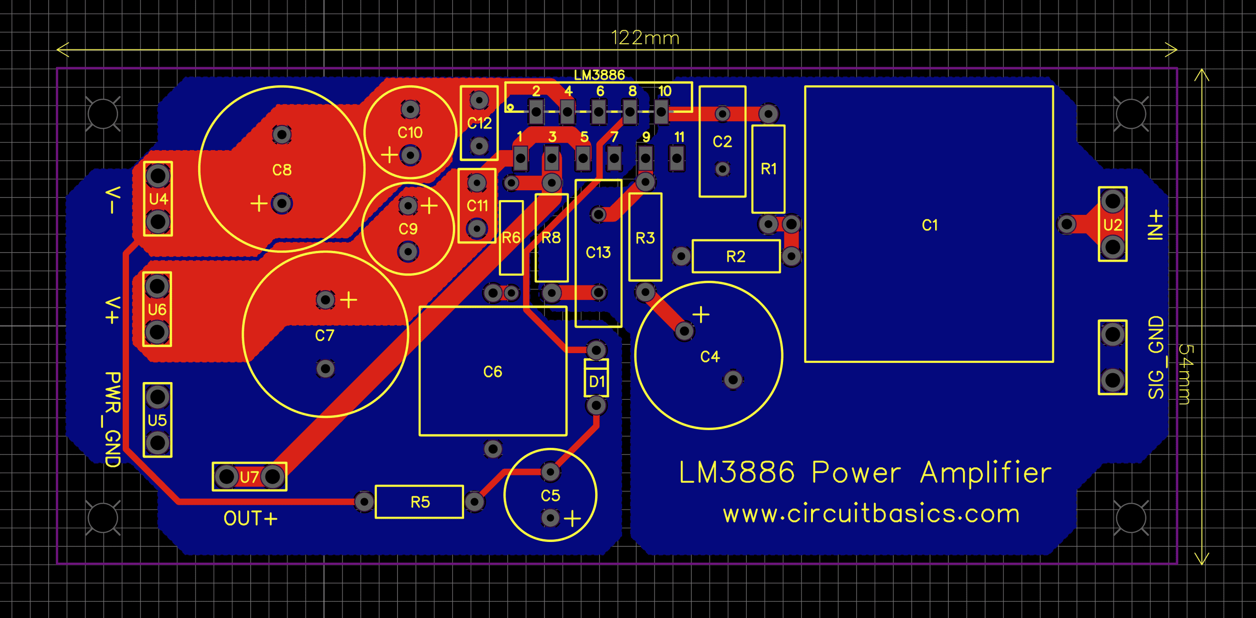
When designing the layout, it’s important to consider the size and shape of the PCB, the number and type of components, and the routing of traces. The layout should be optimized for maximum efficiency and ease of manufacturing. You should also try to group components together based on their functionality and minimize the length of the traces between them. Before routing your traces, it is a good idea to place your drill holes (mounting and vias). If your circuit board design is complicated you may need to modify at least some of the via locations during trace routing.

No comments:
Post a Comment